Pressure Measurement
Measuring Flow in Liquids with Pressure Transducers
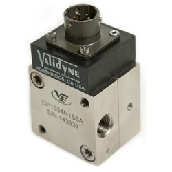
Differential pressure transducers have been widely used to measure flow rate of in-compressible liquids such as water. The most common method is to measure the pressure drop across an orifice plate in the pipe and calculate the flow rate. An orifice plate is simply a plate installed in the pipe, usually between flanges, that has a hole of a known size in the center. As the fluid flows through this, a pressure drop is developed across the orifice plate from the upstream side to the downstream side. This pressure drop is proportional to the flow rate and the transducer signal can be used to calculate the flow rate in engineering units.
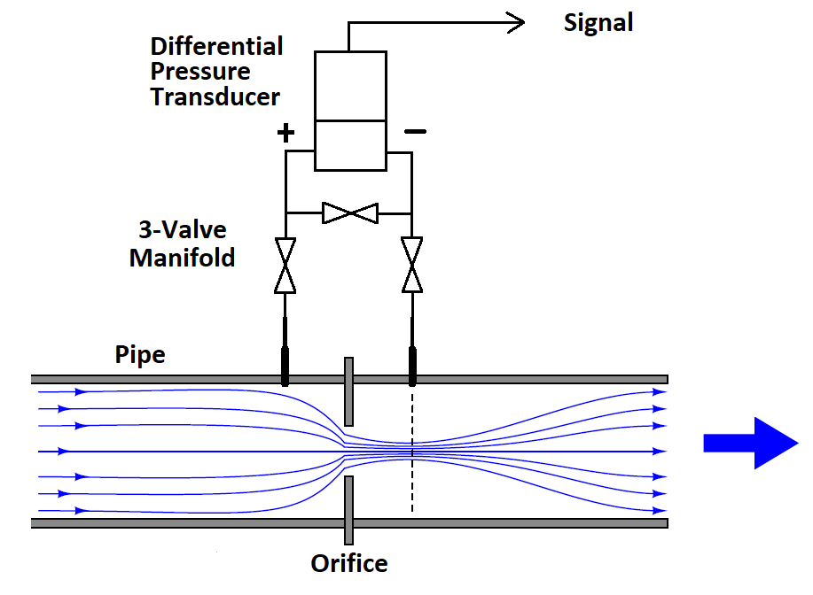
A typical orifice plate configuration is shown in the figure. The upstream side of the orifice will have the higher pressure and is connected through a three-valve manifold to the + port of the pressure transducer. The downstream side of the orifice is similarly connected to the – port of the pressure transducer. The three valve manifold is used to protect the pressure sensor from over-pressure when installing the pressure sensor into a working pipe.
The calculations for determining the flow rate from the pressure drop are derived from fairly straightforward physical equations. There are a number of variables, however, each with their own engineering units. These include: orifice geometry, pipe dimensions, fluid viscosity and fluid density. Given the number of terms and the conversion factors involved for each of the variables, the calculations can get quite involved. Fortunately there are a number of on-line calculators that let you simply enter the variables in whatever engineering units are convenient, and then calculate the flow rate for any given pressure drop across the orifice.

Typical Orifice Flow Calculator
By determining the flow rate for a series of pressure drops, a table can be constructed that shows the relationship between flow rate and, ultimately, the signal from the transducer. From this, a simple equation can be devised that converts the pressure transducer output signal into engineering units of flow.
An example will illustrate how this is done
A 6” ID pipe is used to pump water at rates from 200 to 600 gallons/min. An orifice is installed with a 4 inch diameter and standard corner taps. The fluid density of water is 8.345 lbs/gal and the viscosity is 1 centipoise. By entering a series of pressure drops into the calculator, a table of resulting flow rates can be made, as shown below:
DP, In H2O GPM
100 640
50 453
25 321
10 203
So a differential pressure transducer calibrated from 0 to 100 In H2O will cover the pressure drops expected across the orifice plate for the flow rates to be measured. If the pressure transducer signal is 0 to +5 Vdc for 0 to +100 In H2O, then we can extend the table as follows:
DP, In H2O GPM Signal, Vdc
100 640 +5.00
50 453 +2.50
25 321 +1.25
10 203 +0.50
Notice that the relationship between flow and pressure drop is not linear. Happily, it can be expressed by a simplified version of the Bernoulli Equation:

Flow Equation Given ΔP in In H2O:
Q is the flow rate, ΔP is the pressure drop and k is the orifice coefficient that rolls in the effect of all the other variables. We can solve for k by simply dividing the flow rate by the square roof of its associated pressure drop. From the top line of the table:
k = GPM/√(ΔP)
k = 640/10 = 64
We can verify this by using the new value of k to determine the flow rate, Q, in another part of the table, say at 25 In H2O:
Q = 64 (5) = 320 GPM
The value of k can be verified across the full calibrated range of the pressure transducer with as many other points as desired.
Flow Equation Given the Signal in Vdc:
The same can be done for the relationship between flow rate and square root of the signal. Starting again with top row of the table, the square root of 5 V = 2.236.
k = 640/2.236 = 286.217
Verifying at 50 In H2O, or 2.5 Vdc:
Q = 286.217 (1.581) = 452.5 GPM
For this example system, the flow rate can be determined from the transducer voltage signal as follows:
GPM = 286.217 (√Vdc)
Flow Equation Given the Signal in mA:
A pressure transducer signal of 4 to 20 mA can also be used, but the offset of 4 mA at zero differential pressure presents a slight complication in that 4 mA must first be subtracted from the signal reading before the square root is taken. Using the same example, we first start with a table showing differential pressure in In H2O. flow rate in GPM and the signal in mA:
.DP, In H2O GPM Signal, mA
100 640 20.00
50 453 12.00
25 321 8.00
10 203 5.60
Solving for a new k that gives us flow as a function of mA, we have:
k = GPM/(√(mA-4)) = 640/(4) = 160
Substituting this new value of k into the equation for a different signal in the table, we can confirm at 8 mA:
GPM = 160 (√(8-4)) = 160 (2) = 320 GPM
So for a pressure transducer with a 4-20 mA output we have the following general flow equation for this example:
GPM = 160 (√(mA-4))
These equations and the various factors affecting flow through an orifice are thought to yield flow rates that are accurate to about 1% – that is why there is sometimes a GPM or two difference in the results.
Things to Consider:
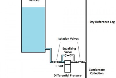
There are a few practical considerations to keep in mind. A three-valve manifold must be used in conjunction with an orifice plate and a differential pressure transducer installation. This allows the pressure transducer to be put into service while the pipe is pressurized. This is accomplished by attaching the pressure transducer + and – ports to the closed isolation valves while the equalizing valve is open. The isolation valves are then slowly opened, exposing both sides of the pressure transducer equally to the static pressure inside the pipe. The open equalizing valve eliminates any possibility of a high differential pressure being applied to the transducer. When the pressure transducer is fully connected, the equalizing valve is closed so that the differential pressure across the orifice plate is sensed by the pressure transducer.
To remove the pressure transducer from service, the equalizing valve is first opened followed by the closing of the isolation valves. When the isolation valves are fully closed, any residual pressure in the sensor cavities is bled down through the pressure transducer bleed ports. The equalizing valve is then closed as well, and the pressure transducer may be disconnected from the manifold. Note that everything must be done exactly in this sequence – the equalizing valve is the first thing to be opened when valving the pressure transducer into service and the last thing closed when valving the pressure transducer out of service.
Material compatibility is another consideration. 316 SS wetted parts are the best choice for pressure transducers to be used to measure water flow. Validyne can also provide Inconel wetted parts for more corrosive liquids. The O-Ring material in the pressure sensor body must also be compatible with the liquid, and Validyne can offer a wide variety of elastomer compounds.
Orifice flow measurement is considered to be most accurate for pipe sizes greater than 2 inches ID. The orifice plate must be located in a straight run of piping, away from elbows or tees. The pipe leading up to the orifice plate should be straight for several pipe diameters. Gaskets for the orifice plate flanges must be carefully aligned and not allowed to impede the flow inside the pipe as this can introduce an error in the measurement.
There are other flow measurement technologies including paddle wheels, turbine meters, electromagetic types and many others. The orifice plate and differential pressure transducer systems have persisted because of low cost and maintenance combined with a reasonably accurate result over a wide range of pipe sizes, liquid types and flow rates.

Leave a reply
You must be logged in to post a comment.