Oil & Gas, Pressure Measurement, Utility
Tech Brief: Transducer Isolation
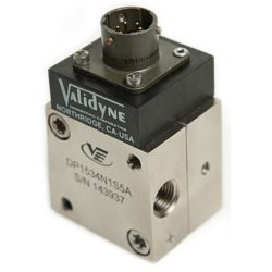
Validyne pressure transducers are designed and built to be electrically isolated from the fluids they measure. This is done by protecting the inductive sensing coils inside the sensor body with a welded cover and using isolation feed-throughs for the coil wires. This is done because often the plumbing connected to the transducer will be at a different ground potential than the electronics powering the sensor. Isolation insures that any difference in ground potential between the sensor body and the electronics receiving the transducer signal will not cause instability in the readings or damage to equipment connected to the transducer wiring.
A loss of isolation will affect the transducer readings, often causing drift or noise in the pressure signal. If a transducer is malfunctioning or exhibits an unstable signal the first thing to check is the transducer isolation. This is very easy to do:
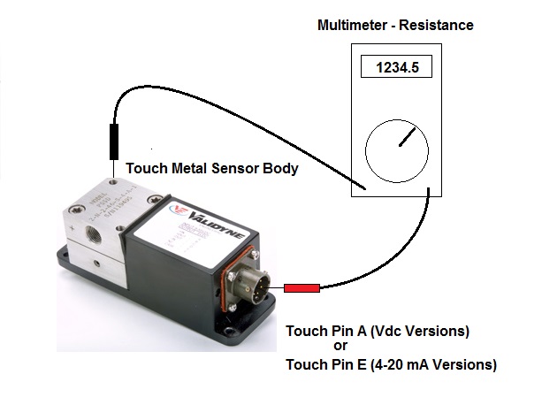
1. Take a standard electrical multimeter and put it in the DC resistance measurement mode.
2. Remove the mating connector from the transducer, exposing the pins on the transducer connector.
3. For VDC output type transducers (P55, P24, etc) place the red probe of the multimeter on pin A of the exposed transducer connector (or pin E for 4-20 mA versions). Also use Pin A for all variable reluctance sensors such as the DP15 or DP360/363.
4. Touch the black probe to the metal sensor body.
5. Measure DC resistance.
The DC resistance should be infinite or at any rate very high. An open circuit indication also means the sensor isolation is good. If the DC resistance is below 100 K Ohms, the sensor will likely exhibit drifting or noise. A low resistance or a short means the sensor will not provide an accurate reading.
Comments are closed

