Pressure Measurement
Selecting Accessories for the Recalibrating the P55 Pressure Transducer
Introduction:
The Validyne P55 pressure transducer has as its sensor a variable reluctance pressure sensor that can be re-ranged for different full scale pressure measurements. The sensor can be disassembled, a new sensing diaphragm installed and the unit re-calibrated to the new full scale pressure. Some 23 different full scale pressure diaphragms are available and this application note will describe how to select and order the parts needed to re-range the sensor and interface the signal to a PC.
Sensor Parts:
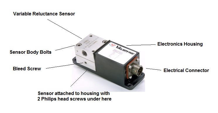
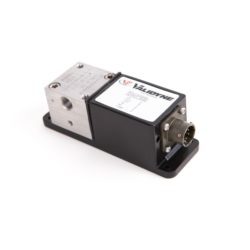
A typical P55 is shown above, with the external parts identified.
First, remove the two Philips head screws holding the sensor to the P55 electronics housing. These are located on the underside of the housing. The wires from the sensor to the electronics are very short, so take care they do not break.
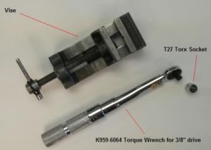
To disassemble a P55 sensor a torque wrench, T27 Torx socket and a vise are needed. The tools needed to disassemble the sensor are available from Validyne and are shown below:
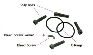
The sensor can be disassembled by removing the four 10-32 Torx T27 body bolts. When disassembled, the sensor body pieces separate and the sensing diaphragm and o-rings are removed. These parts are shown below:
It is good practice to replace the body bolts and o-rings when changing the range of the P55. Various o-ring compounds are available (see ordering chart).
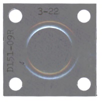
The sensing diaphragm may now be replaced with one of a different range. A typical sensing diaphragm is shown below:
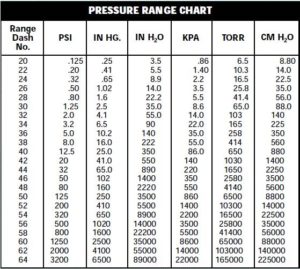
To re-range a P55 sensor the full scale pressure must be known and the correct diaphragm part number ordered. The part number for a P55 diaphragm starts with 3- and is followed by a two-digit range code. The diaphragm in the photo above is p/n 3-22 and has a full scale range of 5.5 In H2O. The other available range codes for the P55 sensing diaphragm are shown in the chart below with their full scale pressures expressed in various engineering units.
Re-assembly is simply the reverse of dis-assembly, taking care that the torque on the body bolts is 125 In-Lb. The vise is used to stabilize the sensor body during assembly and to allow the torque to be correctly transmitted to the body bolts.
Also be sure that the bleed screws are tightly seated – these use a 5/64” hex wrench, Validyne p/n K950-0781. The sensor is reattached to the housing using the two Phillips head screws.
Calibration Accessories:
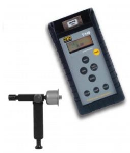
The next step is to calibrate the P555 against a pressure standard. Validyne can supply model T140K calibrator kit that includes a pressure pump and reference standard – an example is shown below.
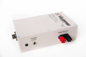
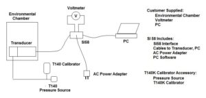
The T140K calibrator kit is available in six different versions covering the available DP15 full scale pressure ranges. To calibrate theP55 connect it the SI58 digital interface and have a voltmeter to observe the analog output signal of the P55 as it appears on the binding posts of the SI58.
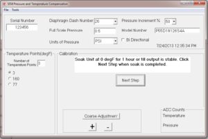
The SI58 connects to any USB port on a PC and is supplied with software that allows changing the internal registers of the P55 to achieve an accurate calibration. Connect the re-ranged P55 to the SI58 and the SI58 to a PC. Connect a multimeter to the SI58 binding posts to observe the P55 output signal.
Load the calibration software and follow the instructions for applying zero and full scale pressures using the T140K calibrator. The software will adjust the P55 microprocessor correction factors to produce an accurate calibration with the new sensing diaphragm.
The SI58 software also allows the user to compensate the P55 through temperatures. The temperature range can be selected by the user as applied by an environmental chamber.

Leave a reply
You must be logged in to post a comment.