Data Acquisition, Pressure Measurement
Interfacing 4-20 mA Current Loops to the USB2250
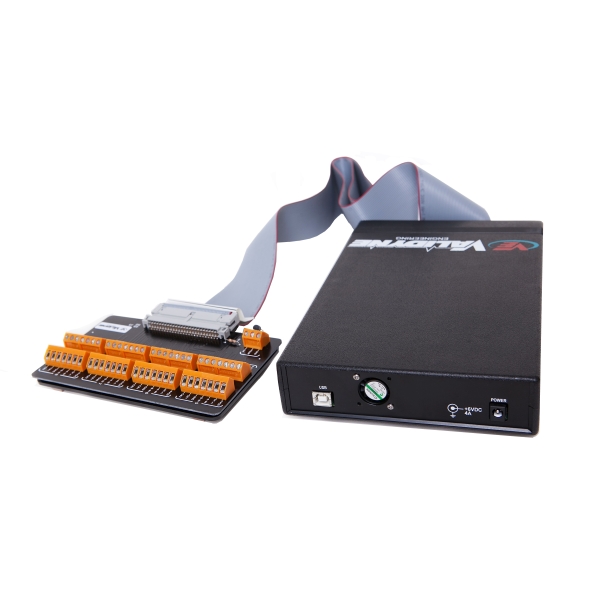
Many pressure transducers and other field instruments use the two-wire 4-20 mA current loop for both power and signal. The 4-20 mA current loop is economical to install, using the same two wires for power and signal. It is also ideal for sending a signal over long distances – up to a mile or more – with high resistance to noise. Most data acquisition devices, however, are configured to accept voltage signals. This application note will describe how to interface a standard two-wire 4-20 mA current loop to the USB2250 sensor interface.
A typical 4-20 mA transmitter receives power from an external power supply. The power supply must be able to provide enough voltage and current to power the transmitter under all operating conditions. The transmitter will require some voltage just to produce a signal and the power supply must provide this plus any power needed to overcome any resistances placed in the current loop. The maximum amount of current required by the transmitter will be at least 20 mA, but it is best to select a power supply that will provide for 25 or 30 mA through the loop to allow for over-range indication by the transmitter.
To interface to a data acquisition device such as the USB2250 a resistor is placed in the loop and the voltage drop across the resistor will be connected to the USB2250 as a single-ended voltage input. To see how this works, assume the following conditions:
Minimum voltage required by the transmitter = 12 Vdc
Maximum loop current = 25 mA
Interface Resistor = 250 Ohms
Wire or other miscellaneous resistances in the loop = 20 Ohms
To calculate the voltage required for the power supply, we add up the voltage drops in the loop:
12 Vdc for the transmitter
Voltage drop through the wire = 0.025 * 20 = 0.5 Vdc
Voltage drop through the interface resistor = 0.025 * 250 = 6.25 Vdc
Adding these voltage drops together, the minimum voltage provided by the power supply must be 12 + 0.5 + 6.25 = 18.75 Vdc to push 25 mA through all the resistances in the loop. For a single loop the power supply will need to be rated for at least 18.75 * 0.25 = 0.47 W, but typically a single power supply will power many loops before wattage ratings become an issue. We can use a 24 Vdc power supply – just as long as it is greater than 18.75 Vdc.
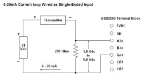
The diagram below shows how the current loop is interfaced to the USB2250 terminal block. Note that the power return is common to the USB2250 signal ground. The voltage drop across the resistor is 1 Vdc when the signal is 4 mA and 5 Vdc when the signal is 20 mA, being proportional in between.
USB2250 scale and offset factors in Easy Sense software are used to convert the 1 to 5 Vdc input into engineering units. If, for example, the 4-20 mA signal is for a 100 psig pressure transducer, then at an input of 1 Vdc the pressure is 0 psig and at 5 Vdc the pressure is 100 psig.
The algebra is simplified by first determining the scale factor = change in pressure/change in voltage = 100/4 = 25.
Multiply the scale factor by -1 to obtain the offset factor: 25 * -1 = -25.
Check by determining the readings at each end point:
At 1 Vdc the reading will be R = (25 * 1) -25 = 0 psig
At 5 Vdc the reading R = (25 * 5) -25 = 100 psig
The USB2250 will read the input from the current loop and provide readings in psig or any other engineering units.
Comments are closed

