Data Acquisition, University
Connecting Strain Gages to the USB2250
Strain gages are sensors that change in resistance proportional to the strain of the item to which they are affixed. Strain gages can also measure the stress at the points they are attached and have been used extensively in aircraft frame testing and other structural studies. The relationship between stress, strain and resistance change as well as the proper way to use a strain gage in a circuit to interface to data acquisition can be a complicated subject. Here is a simplified look at the use of strain gages and how to connect them to the USB2250.
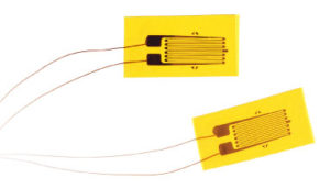
A typical strain gage, as shown below, is a very thin piece of wire bonded to flexible backing material with pads for connecting the strain gage into a circuit.
The strain gage is affixed with epoxy to the structural piece that is to be measured. Strain gages are normally available in 120 Ohm, 350 and 1000 Ohm resistances. The change in resistance of a strain gage in use is often very slight, typically less than 1 Ohm. The bonding of the strain gage to the structural piece must be very tight so that small amounts of strain are efficiently transmitted to the gage – and this is something of an art.
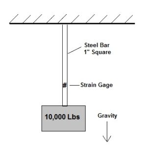
So how much change in resistance will occur in a typical application? Here is a simple example: a 1 inch square bar of steel is loaded with a 10,000 lb weight. If a 350 Ohm strain gage is affixed to one of flat sides, what will be the resistance change?
The first thing to do is calculate the stress on the structural part to which the gage is affixed, and that is simply the force applied divided by the area.
S = F/A
Where:
S = Stress, psi>br />
F = Applied Force, Lbs
A = Area, Sq In
In this case 10,000 lbs/1 sq in = 10,000 psi.
How much strain occurs? Strain is expressed in inches per inch, and is a dimensionless number. It is simply the number of inches of strain that occurs over every inch of length in the direction of the load. A 10,000 lb load on a 1 foot long bar will have less total strain than the same load on a 100 ft long bar. But the amount of strain per unit length is constant.
E = S/M
Where:
E = Strain, inches per inch (dimensionless)
S = Stress, psi
M = Modulus of elasticity, dimensionless
In this case the strain is 10,000/30,000,000 = 3.333 e -4 inches per inch.
Where 10,000 is the applied force in psi and 30,000,000 is the modulus of elasticity for steel.
Once the strain is known for the applied load, the change in resistance can be calculated.
dR = Rsg * GF * E
Where:
dR = Change in resistance of the strain gage, Ohms
Rsg = nominal resistance of the strain gage, Ohms
GF = Gage Factor of the strain gage (stated by the manufacturer but usually about 2)
E = Strain, inches/inch
Assuming a gage factor of 2, the change in resistance in Ohms = 350 * 2 * 3.333 e-4 = 0.233 Ohms. So in this case the change in resistance of the strain gage is just one quarter of one ohm out of to total strain gage resistance of 350 Ohms.
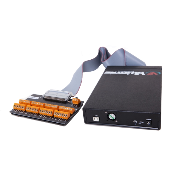
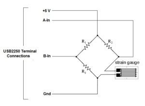
The USB2250 can measure such small changes in resistance when the strain gage is configured in a Whetstone Bridge circuit and connected to the USB2250 terminal block.
Note that there are a total of four resistances in the Whetstone bridge and only one is the active strain gage. This is called a quarter bridge configuration. Each of the other resistances must be 350 Ohms exactly, and these are called completion resistances. Completion resistor networks are provided by strain gage manufacturers. The quarter bridge interface to the USB2250 is shown below:
In this example, the strain gage resistance has changed from 350 Ohms at no load to 350.233 Ohms when 10,000 pounds is applied to the bar. The output signal of the Whetstone bridge is calculated as follows:
Vb = ((Ve * Rsg)/(R2 + Rsg)) – (Ve/2)
Where:
Vb = voltage output of the bridge, Vdc
Ve = USB2250 excitation voltage, Vdc = 5
Rsg = Rsistance of the strain gage, Ohms = 350.233
R2 = Completion resistor, Ohms = 350
So the circuit in this case produces just 0.83186 millivolts at full load.
We can also express that as millivolts output per volt of excitation, or mV/V:
mV/V = 1000 * (Vb/Ve)
So the USB2250 will receive 0 to 0.1664 mV/V of signal from this circuit as the bar is loaded from 0 to 10,000 lbs.
If we wanted the USB2250 to indicate the weight applied to the bar – making it into a kind of a scale – than we can determine the scale factor needed to convert the mV/V reading into pounds of force:
Lb = mV/V * SF
Where:
Lb = Applied force in pounds
mV/V = signal from Whetstone bridge
SF = Scale Factor
Re-arranging this we get SF = Lb/mV.V = 10000/0.1664 = 60106
By entering 60106 into the Scale Factor box in the USB2250 software, we will now receive the readings as pounds of force applied to the bar.
Comments are closed

