Pressure Measurement
Basics of Validyne Pressure Sensor Calibration
A pressure sensor is a device that changes pressure into an electrical signal. That electrical signal is only useful if it accurately represents the pressure applied to the sensor. Calibration is the process by which the sensor electrical signal is adjusted so that it has a known relationship to the applied pressure. After calibration the electrical signal can be measured and that can be used to determine the pressure at the sensor.
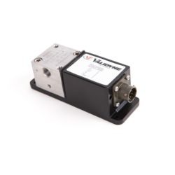
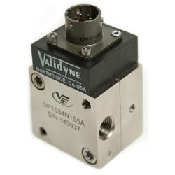
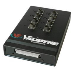
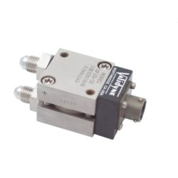
The electronics that support Validyne pressure sensors are called carrier demodulators. These connect to the transducer and – once calibrated – provide a DC signal that will be proportional to the pressure at the transducer. Typical Validyne pressure sensors are models DP15 Range Changeable Pressure Sensor, DP45 Low Pressure Differential Pressure Sensor, DP103 Very Low Pressure Sensor or DP360 High Line Pressure Sensor. Typical carrier demodulators for these sensors are CD15 Carrier Demodulator, CD17 USB Carrier Demodulator, CD23 Signal Conditioning with LED Display, CD280 Multi-Channel Carrier Demodulator or CD379 Portable Carrier Demodulator.
Note that the calibration is done as a system – transducer, cable and electronics together. We are often asked, but cannot provide, calibrated sensors. The calibration must be done with the transducer and electronics connected together.
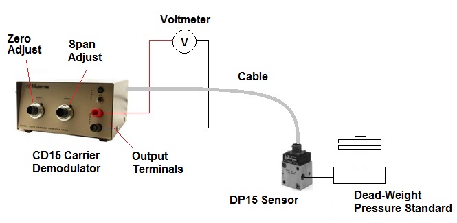
Calibration adjustments for Validyne sensors involve two parameters: zero and span. These adjustments are located on the carrier demodulator. For the CD15 carrier demodulator, for example, the zero adjustment sets the output signal to 0 Vdc when the pressure applied to the sensor is 0. The span adjustment is used to set the output signal to +10 Vdc when the full scale pressure is applied to the sensor. The 10 VDC output signal is read with a voltmeter connected to the front-panel binding posts.
Here is a typical sequence:
- Connect Voltmeter to the output terminals of the carrier demodulator
- With zero pressure applied to the transducer, turn the Zero adjustment until the voltmeter reads 0 Vdc
- Apply full scale pressure to the sensor.
- Turn the Span adjustment until the output at the voltmeter reads +10 Vdc.
- Bleed out the pressure and check the zero pressure reading again – adjust to 0 Vdc as needed.
Tolerances on the voltmeter readings are typically +/-0.005 Vdc.
The pressure applied to the transducer should be known to an accuracy of 0.05%, if possible. Pressure standards for calibration of transducers can be a slant manometer, dead-weight tester or more sophisticated devices. The important thing is to be able to apply a known pressure.
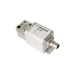
The typical calibration setup is shown in the above image.

Leave a reply
You must be logged in to post a comment.