medical, University
Basics of Pneumotach Flow Measurement
Introduction:
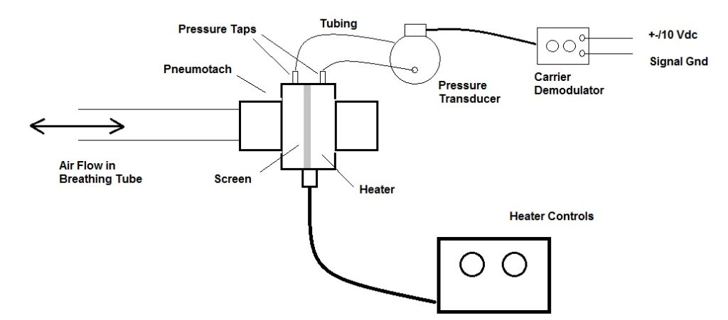
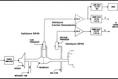
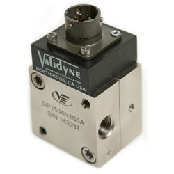
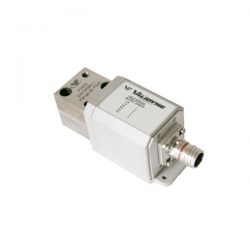
Pulmonary function testing is a medical diagnostic procedure that measures how much air you are breathing and how fast. These parameters are measured with a device known as a pneumotach. A pneumotach is essentially a light screen that is inserted in the airflow. The pneumotach creates a known pressure drop that is directly proportional to the air velocity. A pneumotach is connected to an air tube that allows the patient to breath freely. As the air moves in and out of the patient’s lungs the flow of the air creates a small drop in pressure across the pneumotach screen. A sensitive pressure transducer, like the Validyne DP45, is connected to the pressure taps of the pneumotach and produces an analog signal proportional to the flow rate. This signal is integrated to volume so that the amount of air and its flow rate into the lungs is known at each instant in the inspiration/expiration cycle. The pneumotach typically is equipped with a heater to keep condensation from forming on the pneumotach screen. A typical system is shown above.
Typical System:
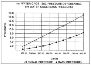
The key to quantifying these measurements is knowing the relationship between flow rate and pressure drop across the pneumotach screen. Pneumotachs come in several sizes, depending on the patient size. A pneumotach used for measuring lung capacity of an adult athelete will be different than a pneumotach designed to measure breathing in premature infants. It is important, of course, to select the correct pneumotach size for the intended measurement. In any case, every pneumotach style will have a chart showing the relationship between air flow and pressure drop. An example is shown below.
Calibration:
The Validyne transducer measures differential pressure so the conversion of the pressure signal to flow is a matter of some simple algebra. For example, the pneumotach chart above states that the pressure drop across the pneumotach will be 17 mm H2O at a flow rate of 800 L/Min. The Validyne DP45 in its most sensitive range, is calibrated such that 20 mm H2O = 10 Vdc signal output. Since the pneumotach flow/pressure curve and the DP45 transducer are nominally linear, we can easily convert the output signal of the DP45 demodulator from volts to L/Min, as follows:
800 L/Min = 17 mm H2O and the signal from the DP45 demodulator is 10 * (17/20) = 8.5 Vdc at this flow rate. Therefore flow in L/Min = 800/8.5 = 94.12 * Vdc So the data acquisition system simply needs to multiply the DP45 output signal in volts by 94.12 to have the flow rate in L/Min.
Comments are closed

